How Do You Know if Your Breadboar Is Functing Correctly or Not

When you lot start on your electronics journey, you will eventually need to wire upwardly some parts to follow along with some project. And, chances are, y'all volition be prodded towards using a breadboard. These ubiquitous pale slabs of plastic are everywhere when information technology comes to electronics hacking.
Their popularity is not surprising - they are like a cutting board is to a cook, or a sewing machine to a tailor: indispensible, multi-purpose, durable, and cheap!
Just virtually every beginner kit contains one, and almost all projects brand utilize of i! Heck, I would not be surprised if you already had one sitting on your work desk. Possibly that's why you lot are reading this guide?
Well you are in luck because nosotros will be spending this tutorial on but breadboards, with diagrams, tips and tricks to have you frombeginner to brilliant

You lot are probably wondering how on earth a piece of plastic that fits in your hand relates to the large slab of wood used to bake or cut bread.

A good question! It turns out that many many years agone, for engineers working on electronics earlier 1970 they did not the thing we call a solderless breadboard. Instead, they would build electronics by literally hammering nails into a wooden board - sometimes information technology was too literally a breadstuff lath merely usually but a plank purchased from a hardware store.
Once it was cut to the right size, the electronic parts would be nailed or glued to the board and electrical connections made by soldering or wrapping wire effectually the nails

Since, back so, the components were large and the circuits were simple, it worked out OK. The large wooden board gave mechanical strength and support to project
You can fifty-fifty spotter Collin try out this former-school technique in this video:
While these contraptions looked very absurd - they were somewhat permanent and were not good for complex circuits. Likewise, parts got smaller and smaller so that you couldn't easily nail them down to a chunk of wood.
~~ Interlude ~~ (Wire Wrapping)
For a while in the 1960s to function of the 1980s, engineers and makers used another techniques like wire-wrapping which solved the 'circuitous circuits' issue but was still semi-permanent. It also required a fairly pricey wire-wrap board or the use of wire-wrap pins and sockets.
With do, wire-wrap prototyping could be fast but took a while to go used to:
- parts were wrapped on the reverse side of the board and so yous would constantly flip back and forth
- undoing or fixing a wire wrap could be annoying if in that location were other wires wrapped onto the same pin
- reusing a wire-wrap board was a real hurting since all the wires would have to be advisedly unwrapped or cut.
Here'south an example of a wire wrap prototype with a bunch of LEDs from fastlizard4

There's a little tool that helps yous wrap each wire, but once solderless breadboards showed up, (then quick-turn prototyping PCBs!) wire wrapping fell out of favor very fast.
1971 - The Breadboard Is Invented!
And then in the early on 1970's an awesome thing occured. Ronald J Portugal came upwards with this brilliant invention. The BREADBOARD FOR ELECTRONIC COMPONENTS OR THE Like. It was patented 2 years afterward and the patent expired in 1987

It was quickly called the "Solder-less" Breadboard considering no soldering is required to use information technology, and then shortened to plain Breadboard since nobody uses a "solder-full" breadboard.
And that's how the breadboard got its name!
These "solder-less" breadboards are incredibly handy for building circuits. They are durable and reusable and have tons of work space. They not only hold your parts steady, a breadboard too has internal wiring to make connections super fast.
The nearly common type, the "Total Size" breadboard looks similar this:

This undecayed classic hasn't even changed that much since it's invention in 1971!
Basically, a chunk of plastic with a bunch of holes. However, something special is going on inside the breadboard! Although you can't come across it, inside the breadboard are many strips of metallic that connect the rows and columns together.
If you lot look on the back of your breadboard, there's a yellow waxy paper roofing some pasty cream. If you were to peel dorsum that foam you'd see dozens of these metal rows.
(Don't actually practice this, you lot should keep the xanthous paper on your breadboard, we'll sacrifice this one for some photos!)
If you pulled the metal parts out with pliers (once more, don't do this yourself!) You'd see each 1 is a metal clip with petty teeth. The rows have 5 teeth - 1 for each hole on the top of the breadboard. (The ability rails have 50 teeth)
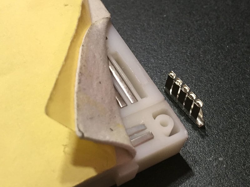
These little teeth are dandy at gripping onto electronic parts. When a office is pushed into the breadboard, the prune pushes open and grabs onto the metal leg. Whatever other parts that are plugged into the other iv teeth are thus electrically connected together

Just most every breadboard is made of three sections: Two sets of very long power rails and the large middle department that is full of those 5-hole-long final strips.

You lot put the components (buttons, LEDs, resistors, integrated circuits, etc) in the middle section, with each pin connected to the rows concluding strip. The power rails are long columns used to distribute the power and ground connections along the entire circuit.
As you build circuits you lot'll quickly find that each function usually needs a connectedness to ability or ground, so having a lot of ability/footing pins available will be very handy. To help you go on track of which rail is ground and which is ability, there's a cherry-red (+) and blue (-) stripe down the sides of the rails. Merely make super-sure you connect positive to (+) and ground to (-) or you're gonna take a bad time!
The expletive of the flaky breadboard
Pitiful every bit information technology may audio, solderless breadboards can be flaky, particularly as they age. If you're having problems with your circuit, it could be that the little metal clips on the inside aren't working well. Endeavor poking it with your finger, or moving it to a different section.
Each prune tin can handle at to the lowest degree a hundred plugs and unplugs before the springiness of the prune slowly weakens and eventually stops gripping so well. You'll know when the breadboard needs replacing considering you wont feel the clip gripping onto the function when you printing it in.
Nonetheless, this takes years to happen. Even if you did take to replace it, breadboards are quite affordable. Most makers take a half dozen different sizes for projects, sometimes dedicating each one to a 'long term' projection and keeping i for playing around.
Half Size
The total size breadboard is skillful for larger projects merely I rather prefer the half size breadboard. These are (surprise!) about half the length of the full size breadboard. It has 30 rows and 400 full connection points
They're cracking for modest projects, you can unremarkably fit a small Arduino-compatible and some sensors and LEDs.

Tiny Breadboard
Sometimes you want to become small-scale - if fifty-fifty the half-sized breardboard is too big for your needs check out the tiny breadboard.

Note that this breadboard does not have power rail! But information technology is really cute, with only 17 rows (170 full connexion points) which makes upwardly for information technology. Skillful for when you just take a few components to wire up similar this lilliputian sound visualizer by Neb Earl

Little Breadboard Bits
I don't even know the proper names of these but they're basically little 'crumbs' of a breadboard, for the simplest configurations
The concluding strips on these babies come out to tabs, we've found you can solder these to a perfboard or wire which might make them useful for adding small breadboarding sections to a perfboard or perma-proto
Large Breadboard

For really big projects, requite yourself some room to work in, with a massive 2250-point breadboard - equivalent in size to three full sized breadboards adjacent.
The breadboards are mounted onto a metal plate, and comes with four colored posts you tin can use with a bench-top supply. Four bumpers are included, to proceed the lath from slipping around your desk-bound.
Many of these large breadboards sometimes have 'power rail' that are separate in the middle! That means that if you want to plug in a voltage at the top of the board, it wont appear at the bottom. Since this often trips people upwards, we strongly suggest drawing lines onto the breadboard the moment yous get it! Merely follow this epitome to see where the splits occur. Each drawn red line is a split.
You tin tell if your large breadboard has split rails by using a multimeter (best!) or past looking at the red and bluish painted stripes, if they have a gap in the middle, the rail is carve up!
Lets say you want to practice a very simple circuit, y'all only want to light up an LED using a battery pack. Information technology's a elementary hookup with only 3 parts. Here's the schematic:

- Connect the battery positive (carmine) wire to the positive (longer) leg of the LED
- Connect the shorter leg of the LED to 1 side of the resistor
- Connect the other side of the resistor to the battery negative (blackness) wire.
Despite having only three connections, wiring this up with alligator clips makes for a big and unwieldy tangle of wires


Compare to how neat and organized it is with a breadboard! No long wires, and its easy to swap in a different resistor or LED when you feel similar it


Calculation DIPs and Modules
Wiring up a single LED is no trouble, so lets continue and add more complex components. Parts like DIP (dual in-line pin) fries are a perfect friction match.

When new, the pins are non quite straight, they're bent out a petty like an /--\ shape. Yous can carefully press the pins against a tabletop, and rock them forwards together to bend into a |--| shape

Then carefully press into the center of the breadboard. Lookout man out for aptitude pins!

Yous can remove the chips hands by slipping a sparse screwdriver or awl downward the center ravine/divider and carefully prying upwardly.
Pry from both sides if possible to keep the pins from bending past blow.
There are lots of footling connections inside of your breadboard merely they only go along in rows, basically making each pivot or wire of a part have five full connectedness points. To wire up the parts yous'll need to, um, wire the parts...with wire!
DIY Solid Cadre Wire Jumpers
With non too much effort you can craft your very own artisanal wires!
You'll need a pair of wire strippers, ideally the kind with a bunch of different hole sizes
Nosotros've upgraded our basic 'adjustable' wire strippers to these multi-sized wire strippers. They include: 20-30 AWG strippers, wire cutters, 'plier' tips, and a wire...
And of course, some wire!
Perfect for bread-boarding, free wiring, etc. This box contains 6 spools of solid-cadre wire. The wire is easy to solder to and when bent it keeps its shape pretty well. We like to have...

Most important matter to remember is you lot must apply solid-core wire, ideally 22 American Wire Estimate (AWG).
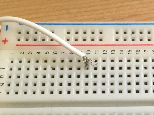
Y'all tin't use stranded core easily considering the threads/strands of the wire volition unravel, shorting with nearby parts by accident

Pick the matching pigsty/slot for the wire you're stripping, and remove well-nigh 1/ii to 1 cm of the plastic roofing off the end
Brand sure y'all don't nick or cut the wire, because that could weaken it.
Cut the other side to length, recall you lot'll need a piffling actress so that you can strip the other end as well!

Strip ane/ii to 1 cm off the other end like before

Voila! A single jumper wire

Plug in both ends into the breadboard as desired to brand an electric connection
There'south cipher wrong with DIY jumpers, and for the neatest looking breadboards, you'll want to use them.
That said, sometimes y'all just want to be wiring ASAP. That's where pre-fabricated jumper wires are really dandy. They're a little more than expensive merely y'all dont need wire strippers and they have these lovely grips.
We have these in a wide variety of lengths and configurations Usually, nosotros similar to outset our breadboard wiring with these and then 'make clean upwardly' with paw-cutting ones once nosotros know the wiring is right and the lengths won't alter
Handy for making wire harnesses or jumpering betwixt headers on PCB's. These premium jumper wires are 3" (75mm) long and come in a 'strip' of 40 (four pieces of each of...
Handy for making wire harnesses or jumpering between headers on PCB's. These premium jumper wires are half dozen" (150mm) long and come in a 'strip' of 40 (4 pieces of each of...
Handy for making wire harnesses or jumpering between headers on PCB'due south. These premium jumper wires are 12" (300mm) long and come in a 'strip' of xl (4 pieces of each of...
OK so you've prototyped your bright invention on a breadboard. Merely yous're no slacker - yous're ready for your next project! You have a few choices: Allow projects 'live' on their breadboard. When done, just purchase a new breadboard and start fresh. Or you could remove all the components and recycle both the parts and breadboard.
- Or at that place's another choice where you transfer the circuitry from the breadboard to a permanent circuit board like an Arduino Proto Shield for example.
- Or you lot may love your project that yous realize that breadboards can slowly rust, and parts can come loose
- Or you lot may want to put your project in a nice box, so you lot need something that is more than durable
For any of these reasons you may want to use a Perma-Proto board. These are basically the non-solderless version of breadboards (solder-full?). You get a sturdy printed circuitboard with almost-identical layout (the rails are closer and in that location'due south more holes)
For instance, hither'due south the half sized perma proto front, back and next to a half sized breadboard

Nosotros basically only took the basic layout of a half-sized breadboard and turned that into a beautiful PCB. The acme side has a white silkscreen, and the same markings y'all're familiar with, to make transferring components piece of cake. The bottom has the 5-hole pad blueprint that matches a archetype breadboard, with 4 ability bus lines on the sides, and no mask and then you can easily cutting traces when necessary.
We used 1.2mm diameter drill holes and so even parts with big leads will fit. All holes are thru-plated for strength and the terminate is a golden plate - y'all won't become oxidation like with bare copper perf lath!
There are besides two mounting holes so you tin can adhere the PCB to your projection box. They'll also fit nicely in an Altoids-sized mint tin
For instance, here is Mike Barela's pro trinket project on a breadboard and and then a finished version that is soldered onto a perma-proto and fastened to an quondam mint-tin

We also have these in a few different other sizes and styles, like a 'quarter sized' 1 that is a bit larger than the tiny breadboard and comes with ability track:
Customers take asked us to carry basic perf-board, just we never liked the await of most bones perf: information technology'south always crummy quality, with pads that flake off and no labeling. Then we...
Full sized breadboard sized, huge with tons of space!
Customers have asked united states of america to carry basic perf-board, only we never liked the expect of most bones perf: information technology's e'er crummy quality, with pads that flake off and no labeling. So we...
And two that lucifer upwardly with mutual mint tins
Making a project that will fit into an "Altoids" Mint Tin? Put downward that PCB shear and option upwards a Perma-Proto in the new heady minty shape!Customers have asked...
Making a project that will fit into an "Altoids Smalls" Mint Can? Or peradventure you just demand a small corporeality of prototyping infinite and a larger breadboard size is too big? Put down...
Connecting the two ability runway
The two sets of runway are not internally connected. Since I nearly always want at least the grounds connected, I like to apply ii solid core wires to make the two sides of rail behave the aforementioned voltages

Heck, I ordinarily get out these on permanently between projects!
While you're at it, it'southward a good idea to add together some capacitors to the track. Electrolytic and ceramic capacitors are normally 2.5mm spacing so they fit right in. A ten-100uF electrolytic paired with a 0.1-1uF ceramic on either side will often be enough for near simple circuitry.

Watch Out For Carve up Rails!
Sometimes you'll get full size breadboards that do non have solid continuous track. This can actually trip upwards beginners because they are used to the basis strip being solid all the fashion down, only there'due south a gap!
Check the silkscreen of the breadboard, if the blue and red lines take a gap, you lot have a split rails

But some breadboards do not have the dainty colored lines so you'll take to test with a multimeter or another manner to verify. Apply little wires to jumper over the gap, if you desire continuous conductivity
Using Fritzing!
We use Fritzing for our diagrams, which tin can brand it very easy to plan out your breadboarding projection without even picking up a wire cutter. Information technology doesn't practice simulation or annihilation, it's but for diagramming - only yous can go from schematic to breadboard or the other way effectually and and so as well generate PCBs.
For complex projects, it can take a crazy tangle of wires and lets you clearly visualize all the connections!

An extra nicety when prototyping with Fritzing is and that the breadboards pins that are "in use" are highlighted green. This can help remind you of what rows are available for other components

Another handy thing is that y'all can click on the breadboard rows and they will highlight all the connected pins including other rows that are internally connected through components! For example, Fritzing knows about the internal connexion in 12mm tactile switches:

This guide was starting time published on Sep 06, 2016. It was last updated on Sep 06, 2016.
murphycomenclater.blogspot.com
Source: https://learn.adafruit.com/breadboards-for-beginners/breadboard-tips-and-tricks?view=all
0 Response to "How Do You Know if Your Breadboar Is Functing Correctly or Not"
Post a Comment